It shall not take into account accidental temperatures which can happen for short duration only, during startup, shutdown, or in emergency conditions, e.g., loss of utilities, valve failure.

The design temperature is usually set 15-20☌ above the maximum continuous operating temperature.

The process engineer defines the design pressure by applying common and reasonable margins above the maximum operating pressure, as shown below.

As such, I'm forced to believe that something unique happened on this vessel whether with the materials, manufacturing or use.These other disciplines are not always aware of the impact of their demands on the cost/lead time of the equipment. I don't see how I can make a case for a design flaw when there is such a long and successful service history of the design. If this was a design issue, I would expect that we would have seen this failure mode occur many times before.
Visual vessel design crack crack#
I am reluctant to believe that this crack is a design flaw mainly because our company has been using this exact vessel design for 40+ years and has 1000+ vessels of this exact design in service without ever seeing this happen before. Thanks for all of the feedback! I really appreciate all of the information. Steris RE: Vessel Repair and Failure Analysis Are there any suggestions of other items to examine or procedures to perform prior to repair? After cleaning and other weld prep, we were going to perform a weld repair. Then we were going to drill the ends of the ground area to blunt the crack in case there's a hairline fracture that we can't see.
Visual vessel design crack plus#
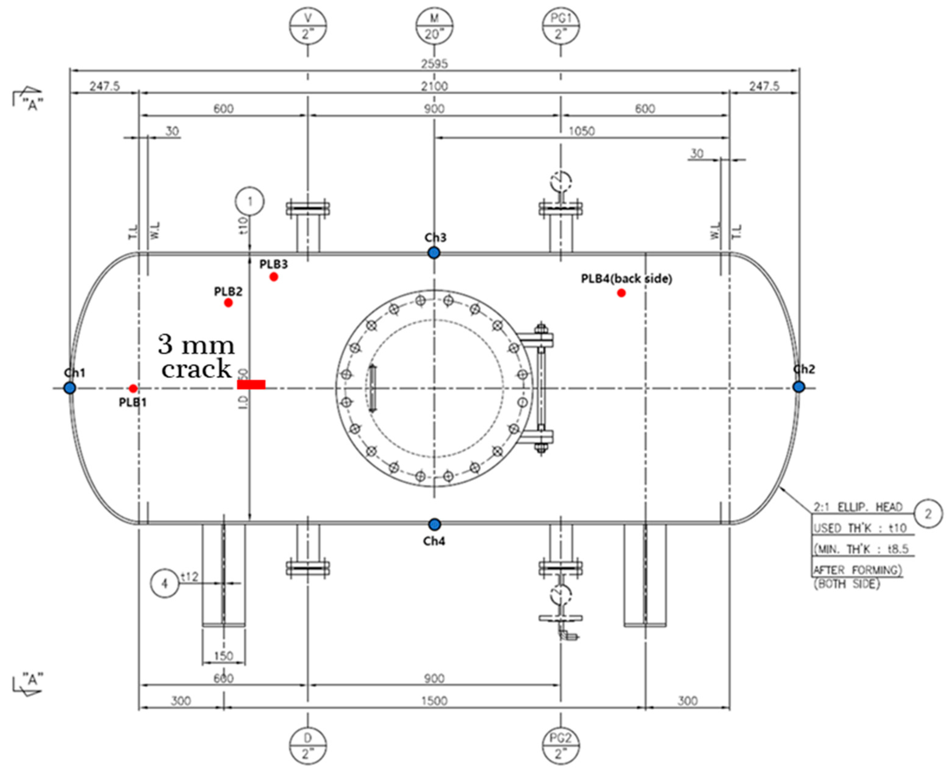
In terms of repair, we were going to grind out the length of the crack plus about 2" on either end. Has anyone else seen anything like this happen? What could be the cause? I was hoping that if something was rolled into the plate that there may have been a tell tale sign on the surface of the material but this doesn't appear to be the case. The material receiving inspection reports don't note anything peculiar during the visual inspection about this plate. My intuition says that this crack is likely a material defect - either an impurity or void that was captured in the rolling process. In terms of operating conditions, the jacket sees saturated steam service at 20-40 psig and has a proof test pressure over 1000 psig. We have thousands of vessels of this design that have been in the field for 40+ years and we have never seen this type of failure before. I'm trying to figure out what happened here. The defect runs parallel to the seam weld/backing bar and is about 3/4" below the edge of the backing bar. The seam weld is backed by an A36 bar that is 1.5" wide. The picture from the field shows that the defect is about 1" below the seam weld. I've attached an illustration of the cross-section of the construction. The vessel is a flat wall cross-section with a stainless steel inner wall, 516-70 jacket (1/4" thick) and A36 support bars between the vessel walls. I attached a picture of the defect for reference.

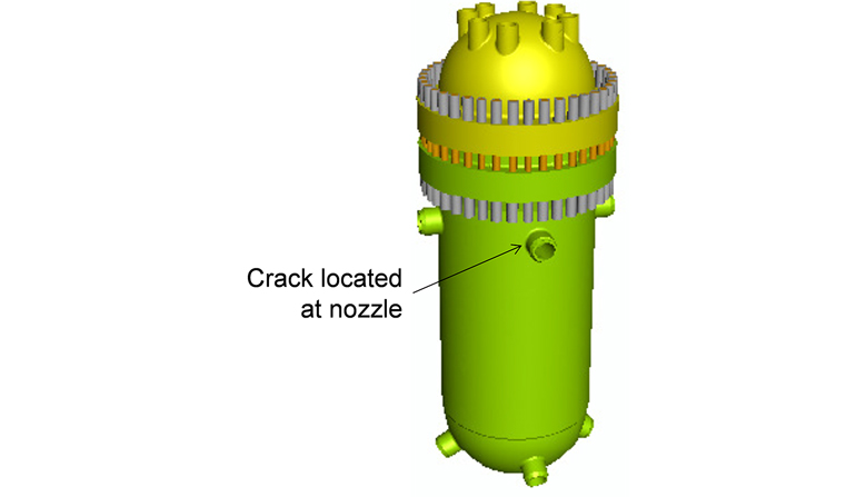
My company has a Section VIII Div 1 vessel that has been in steam service for 2 years and has developed a crack in the jacket.


 0 kommentar(er)
